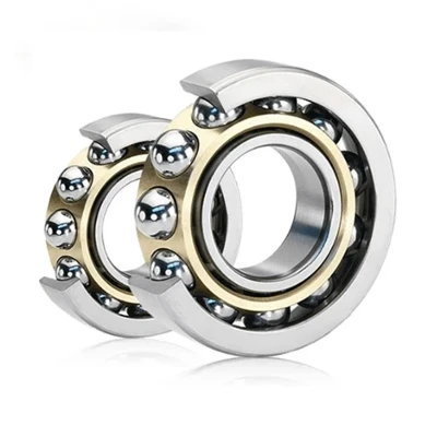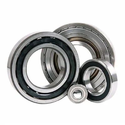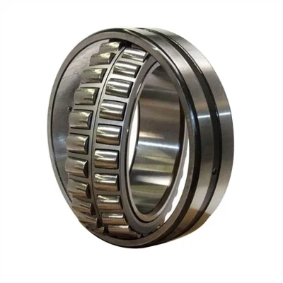



The operating temperature of cylindrical roller bearings depends on a variety of factors, including the amount of heat generated by all relevant heat sources, the rate of heat flow between heat sources, and the heat dissipation capacity of the system. Heat sources include bearings, seals, gears, clutches, oil supplies, and more. Heat dissipation depends on many factors, including the material and design of the shaft and housing, the circulation of the lubricating oil and the external environmental conditions. These factors are described separately in subsequent chapters. Under normal operating conditions, most of the torque and heat of the bearing designation comes from the dynamic loss of elastic fluid at the contact area of the roller/bearing ring. Heat generation is a product of bearing torque and speed. Use the formula below to calculate the calorific value. Qgen = k4N M tapered bearings can calculate the torque using the following formula. M = k1G1 (nμ)0.62 (Peq) 0.3 where: k1 = bearing torque constant = 2.56 x 10⁻⁶ (M in Newton-meter) k4 = 0.105 (Qgen in W, M in Newton-meter) Non-tapered bearings, the calculation method of torque is given in the following sections.
Heat dissipation: How to determine the heat flow of a bearing in special applications is a complex issue. In general, it can be considered that the factors that affect the heat dissipation rate include: 1. Temperature gradient from bearing to housing. This factor is influenced by the size of the housing as well as external cooling devices (e.g. fans, water cooling, etc.). 2. Temperature gradient from bearing to shaft. All other heat sources, such as gears and other bearings, as well as adjacent components, affect the temperature of the shaft. 3. The heat taken away by the circulating oil lubrication system. To some extent, factors 1 and 2 can vary depending on the application. Heat dissipation modes include heat conduction in the system, convection of inner and outer surfaces, and thermal radiation between adjacent structures. In many applications, heat dissipation can be divided into two parts – the heat removed by the circulating oil and the heat dissipated through the structure. The heat removed by the heat dissipated by the circulating oil system is easier to control. In splash lubrication systems, cooling coils can be used to control the lubricating oil temperature.
The heat taken away by the lubricating oil in the circulating oil lubrication system can be calculated using the following formula. Qoil = k6 Cpρf (θo - θi) where: k6 = 1.67 x 10⁻⁵ (Qoil in W) = 1.67 x 10⁻² (Qoil in BTU/min) If the circulating lubricating oil is mineral oil, the heat taken away can be calculated using the following formula: Qoil = k5 f (θo - θi) The following coefficients apply to the heat generation and heat dissipation formulas listed on this page. where: k5 = 28 (Qoil units are W, f units are L/minute, and θ units are °C).
Cheng An Beijing Limited Liability Company
+86-010-56130888
 Language